A technical look at why MIM process capability maps directly to one of precision manufacturing’s most geometry-demanding components, and how to evaluate whether your part qualifies.
The Part and Why It Is So Difficult to Make
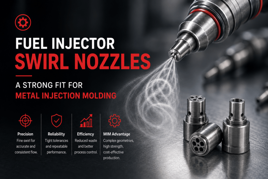
A fuel injector swirl nozzle is a small component, typically under 10 grams, whose entire function depends on precision geometry. Its job is to convert fuel flow into a controlled, rotating spray before it enters the combustion chamber. Getting that right requires internal swirl chambers, fine flow passages with walls as thin as 0.3 mm, tight-tolerance orifices, and intersecting internal channels.
That combination of features is where conventional manufacturing starts to break down.
The Machining Problem
CNC machining handles external features well. But a swirl nozzle is defined by its internal geometry, and those features can’t be reached with a standard cutting tool. Producing them typically requires stacking operations: multi-axis milling, EDM for internal passages, precision drilling, deburring, and dimensional inspection at each stage. On a part this small and this complex, that sequence is slow, labour-intensive, and very difficult to scale economically.
The Material Problem
Swirl nozzles are commonly specified in SS 316L or 17-4PH stainless steel. Both are corrosion-resistant, high-strength, and expensive per kilogram. Machining either grade from bar stock typically removes 60 to 80% of the starting material as chips. On a program requiring tens of thousands of parts annually, that scrap cost adds up quickly, and the geometry doesn’t get any easier to machine as volumes increase.
| KEY CHALLENGE: | Complex internal geometry that conventional tooling can’t reach economically, in a premium material with high scrap rates. These are the two conditions where MIM provides the most direct process advantage. |
What Metal Injection Molding Changes
Geometry Is Formed, Not Machined Away
In Metal Injection Molding, internal passages, swirl chambers, and precision channels are created directly in the tool. Features that would require secondary EDM setups or 5-axis fixturing in machining are simply part of the mold design. The component comes out of sintering as a near-net-shape part with its internal geometry already complete. No secondary material removal needed for those features.
Material Utilisation Changes the Economics
MIM uses only the material required to form the part. There’s no bar stock, no roughing pass, and no scrap pile from material removal. The feedstock, fine metal powder mixed with a thermoplastic binder, is injected into the mold cavity, debinded, and sintered. What you get is a dense, precise component with material properties comparable to wrought equivalents.
Tooling Is a One-Time Investment
Once tooling is qualified, the per-part cost drops as volume increases. For programs requiring 5,000 or more units per batch, MIM consistently outperforms machining on a total cost basis. That comparison isn’t just per-piece price. It includes tooling amortisation, material yield, and the reduction in secondary operations.
| BATCH SIZE VS. ANNUAL VOLUME: | Our minimum order quantity is 5,000 units per batch, which is set by the economics of tooling amortisation. Annual volumes of 50,000 units or above are where MIM delivers its strongest cost-per-part advantage, as tooling cost becomes a smaller fraction of total program spend. |
Meta Build Industries: Verified Process Capabilities
The specifications below reflect our actual production capability across qualified MIM programs. These aren’t theoretical limits. They’re the tolerances and material properties we hold in production, backed by material test certificates issued with every batch.
| ±0.03 mm CRITICAL DIMENSIONAL TOLERANCE | ±1% AS-SINTERED STANDARD TOLERANCE | 0.25 mm MINIMUM WALL THICKNESS | 1.0 mm MINIMUM HOLE DIAMETER | >96% SINTERED DENSITY (THEORETICAL) |
Material Properties: SS 316L
Sintered density: 7.9 g/cc. Tensile strength: 600 MPa. Elongation: 40%. Corrosion resistance is suitable for fluid-handling and marine environments. All material properties comply with ASTM and ISO standards.
Material Properties: 17-4PH Stainless Steel
Post heat treatment tensile strength reaches up to 1,000 MPa, which puts it within range for structural aerospace applications requiring a high strength-to-weight ratio. Material test certificates are issued per production batch.
A note on transparency: The swirl nozzle in this article is used as a capability analysis. It represents the type of component our process is built to handle. We haven’t produced this specific part. If you’re evaluating MIM for a similar fluid-system component, we’ll give you an honest DfMIM assessment based on your actual drawing, including any limitations we identify.
MIM vs Conventional Alternatives: A Direct Comparison
The table below compares MIM against other manufacturing processes on the parameters most relevant to complex, small, high-volume components.
| Parameter | MIM | CNC Machining | Die Casting | Investment Casting |
| Geometric complexity | Very High | High (external) | Medium | High |
| Production volume fit | High volume | Low to Medium | Very High | Low to Medium |
| Dimensional tolerance | ±0.3% | ±0.05% | ±0.5% | ±0.5% |
| Minimum wall thickness | 0.5 mm | 0.5 mm | 1.5 mm | 1.5 mm |
| Material utilisation | Near-net (minimal waste) | 60 to 80% removed as chips | Good | Moderate |
| Internal channel capability | Formed in tool | Limited by tool access | Limited | Moderate |
| Cost per part (high vol.) | Low | High | Low | High |
CNC machining is still the right starting point for prototypes, one-off parts, or geometries that are primarily external. MIM becomes the right process when internal geometry complexity, material cost, and production volume all come together, which is exactly the profile of a swirl nozzle.
The Design Opportunity Most Engineers Leave on the Table
Most conversations about MIM start with cost reduction. That’s a fair entry point. But the bigger opportunity is design freedom.
When machining constraints are removed, engineers can specify geometries that actually optimise fluid dynamics, rather than compromising around what a cutting tool can reach. For a component like a swirl nozzle, this means rethinking channel geometry, orifice placement, and wall thickness distribution based entirely on what the part needs to do.
The question worth asking early in any MIM evaluation: If machining weren’t a constraint, what would this part actually look like?
That question leads to better-performing components. Not just cheaper ones.
When MIM Makes Sense for Your Component
MIM isn’t the right process for every part. Here’s the profile where it consistently delivers a real advantage.
- Part weight falls between 0.5 and 300 grams
- Internal or external geometry is difficult or uneconomical to machine
- Minimum batch of 5,000 units per order; annual volumes of 50,000+ unlock the strongest cost advantage
- Material specification is compatible with SS 316L, 17-4PH, SS 304L, or alloy steels
- Critical tolerances are in the range of ±0.03 mm, or standard tolerances within ±1%
- The application is primarily loaded by fluid pressure or thermal cycling, not high-cycle structural fatigue that requires wrought material certification
A swirl nozzle checks most of these boxes cleanly: small mass, complex internal geometry, premium material, and production volumes that justify tooling investment. It’s a useful reference for the type of component where MIM consistently outperforms the alternatives.
Where MIM Has Limits
MIM parts sinter to 96 to 99% theoretical density. For fluid-handling components loaded primarily by fluid pressure and thermal cycling, that’s entirely adequate. For high-cycle fatigue-critical structural applications, or parts that need specific wrought material certifications, MIM needs a more detailed suitability review. We’ll tell you that upfront, before any commercial discussion starts.
Tooling lead time is also worth planning for. Our tool-to-first-sample timeline is 4 to 6 weeks. If you need prototypes in days, machining is still the right starting point. MIM makes sense when you’re moving toward production volumes with a geometry that’s already been validated.
| Does Your Component Fit the MIM Share your drawing with our engineering team. We’ll give you an honest assessment of process fit, tolerances, and production approach, along with a commercial quotation, typically within 2 working days. Request a DfMIM Review at www.meta-mim.com Or reach us directly: +91 90545 81010 | info@meta-mim.in |
Author: KANAV CHHATBARCEO
META BUILD INDUSTRIES.